


Integration Testing
Integration tests with hardware in the loop provides an effective way to develop embedded software using the agile methodology. By linking integration tests results with system and subsystem requirements, we can automate the verification process, thereby combining agile software development with the V methodology.

Figure 1 - System architecture showing interactions between developer, reviewer, Gitlab instance, ATS server and device under test.
Data Acquisition
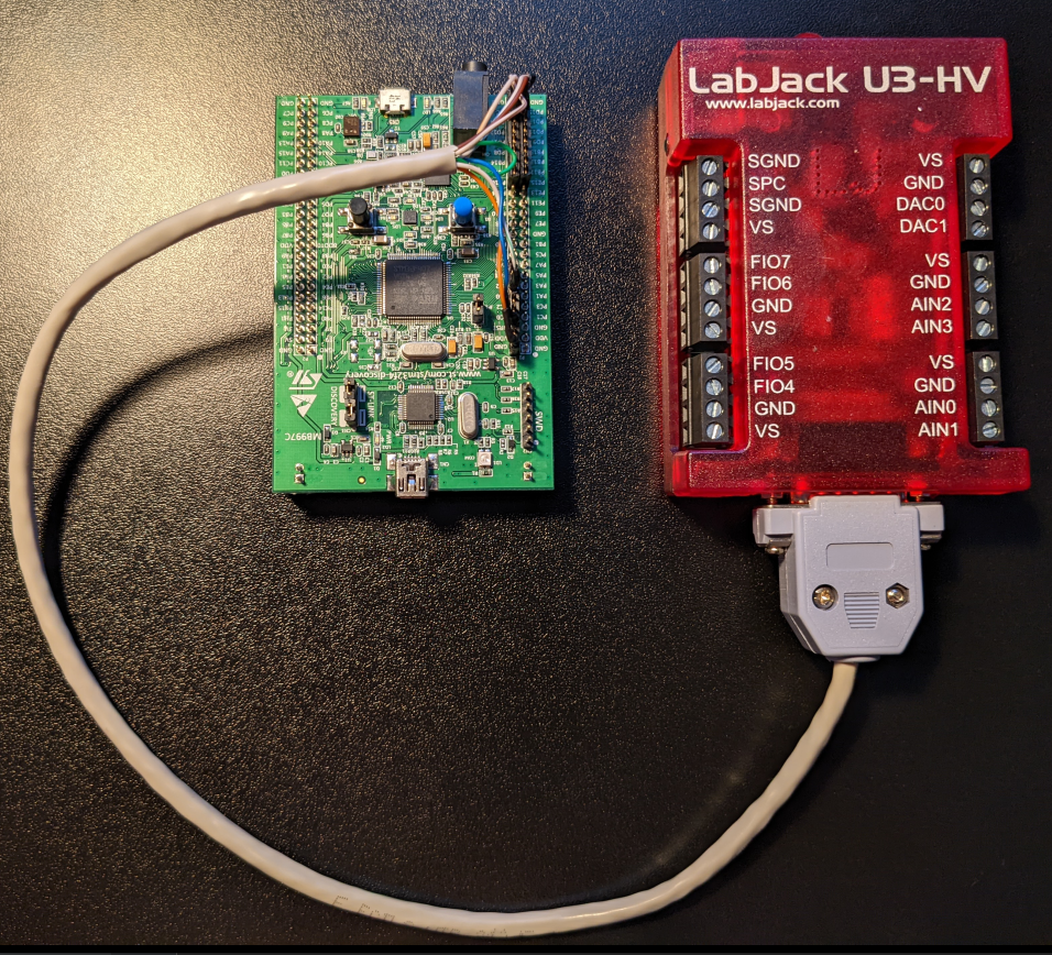
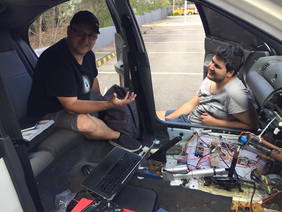
A LabJack U3-HV is used for data acquisition and an STM32F4 Discovery Board is the device under test. Wiring diagram and pinout diagrams below

Fiture 2 - Integration test wiring harness
| Function | Labjack Pin | STM32 Pin | Wire Colour |
|---|---|---|---|
| Reset | EIO6 (output) | NRST (input) | blue |
| User Button | EIO4 (output) | PA0 (input) | green-white |
| Top LED (orange) | EIO0 (input) | PD13 (output) | brown-white |
| Right LED (red) | EIO1 (input) | PD14 (output) | brown |
| Bottom LED (blue) | EIO2 (input) | PD15 (output) | orange-white |
| Left LED (green) | EIO3 (input) | PD12 (output) | blue-white |
| Spare | CIO2 (n/a) | not connected | green |
| Ground | GND | GND | orange |
Software Test Harness Architecture
Integration tests are written in Python using pytest. A 'cradle' class houses mocks for all external devices, in this case we have one mock for GPIO lines. At test time, a test fixture yields the cradle, which exposes methods that can be used to query the physical hardware via the DAQ. At a high-level, the test harness takes the form
Figure 3 - Software test harness building blocks.
DAQ Design
GPIO Mock Design
This simple test repo has one device mock that uses the DAQ to return LED and button states.
Without requirements and design, programming is the art of adding bugs to an empty text file.
― Louis Srygley